The Dial-a-Tempco Exponential Converter
This page is concerned with a novel method of temperature compensation in exponential converters used for synthesizer voltage-controlled oscillators (VCOs). Familiarity is assumed with the basic operation of VCOs and their converters. The reader is also assumed familiar with the "VCO Tempco Theory" page on this site.
Passive temperature compensation of exponential converters -- i.e., compensation using temperature compensating, or tempco, resistors -- has always been a bit of a hit-or-miss proposition. Resistors with the 3350 ppm/K coefficient required to compensate a transistor pair are sometimes difficult to locate and usually have a 10% uncertainty in the coefficient. One may have to settle for purchasing parts with 3000 or 3500 ppm/K nominal coefficients, with actual values being even outside these margins. Additionally, these resistors are sometimes used in a voltage-divider arrangement, resulting in errors in their response. Another problem with past designs is that they usually ignore sources of drift other than the "scale-factor" drift of the transistor pair, leaving substantial amounts of "tuning" drift unaddressed. (The theory of these drift effects is discussed in the Tempco Theory page.) The result of these shortcomings is that designs with tempco resistors often end up with large amounts -- up to 50% of the uncompensated value -- of residual drift.
Based on an understanding of the basic properties of metals, it is straightforward to understand how to correct for tempco inaccuracies with simple circuitry. Basically, one needs to add or subtract a non-compensated voltage proportional to the input control voltage to the base of the converter transistor. This will allow proper scale-factor compensation. In addition, adding a constant voltage to the converter transistor's base can compensate for various sources of tuning drift. In the circuit shown below, the two compensating circuits are adjustable so that the necessary correction voltages can be "dialed in".
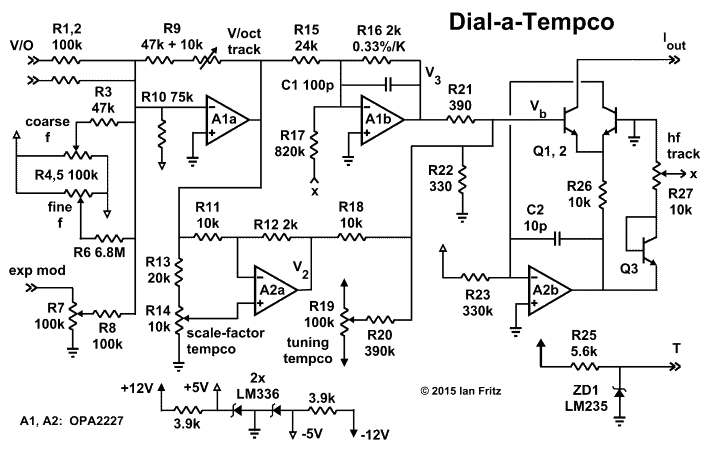
The components on the right side of the figure form a standard exponential converter. Q1 and Q2 are the matched pair that perform the exponential function. A2b is the standard servo amplifier that supplies the reference or standing current, in this case 0.021 mA. Q3, R27 and R17 provide high-frequency tracking compensation. ZD1 is a Kelvin-scale temperature sensor, which may be included temporarily to monitor the temperature of the converter while adjusting the temperature tracking.
The remainder of the circuitry scales the input control voltage (CV) and provides the adjustable temperature compensation. A1a sums all the input CVs. R9 is the usual 1 V / octatve trimming adjustment. A1b, with tempco resistor R16 in its feedback path, attenuates the input signal, providing the nominal scale-factor temperature compensation. The divider R21 / R22 brings the control signal to the required 18 mV per 1 V input. The circuitry around A2a provides the tempco tuning. This is the circuit that cancels the "B" term of the tempco resistor, as described on the theory page. This circuit has a gain that is variable over a range of +/- 0.2. The contribution of A2a's output to the converter's base voltage is about +/- 17% of the nominal voltage. Thus, tempcos between about 2900 and 3900 ppm/K can be compensated.
"Tuning" drift may be compensated by adding a fixed voltage to the transistor base voltage. This voltage is provided by the R19 / R20 combination, which can add about +/- 10 mV to the base voltage, enough to compensate for over 1000 ppm/K of drift.
The converter discussed may be used to control a variety of basic VCO cores. For the following discussion it will be assumed that the oscillator frequency at zero input voltage is fairly high in frequency, around 2 kHz, say. This will ensure that the tempco behavior will be optimized in the frequency region where it is most critical. Adjustment of the circuit requires the following: 1) a digital voltmeter, 2) a frequency counter, 3) a CV reference voltage that can be switched between 0.000 V and 1.000 V and 4) an oven to heat the circuit board.
A simple, inexpensive oven that gives good reproducibility can easily be made at home. Start by finding or buying an Al chassis box and cover that will hold the the VCO circuit board(s), for example a 2" x 4" x 6" box from Bud (available from Mouser.com). Mount the circuit near the center of the box using plastic stand-offs. Heat the box with a drug-store heating pad wrapped around it, using layers of towels and/or newspapers for insulation. It seems best to have a towel between the box and the heating pad. Temperature can be varied by varying the pad's setting, by reducing the line voltage with a Variac or by varying the thickness of the insulating layers. Before starting the adjustment procedure, cycle the circuit up to high temperature (325 K or so) and back a couple of times.
To adjust the circuit, start out with the tempco adjustments at zero, i.e., adjust R14 until V2 is zero and adjust R19's slider voltage to zero. Then adjust R9 and R27 to obtain proper 1 V / octave tracking by the usual method of setting correct octaves at low and high frequencies.
Now measure the VCO frequency at room temperature (RT) with 0 V and with 1 V input voltage. Take several reading and average them. Now heat the circuit up to about 315 K to 320 K and measure the two frequencies again. Make sure the temperature is stable for this measurement and again average several readings. Bring back down to RT and check the first readings.
Next the scale and tuning drifts must be calculated. (Refer to Eqns. 6 and 7 on the theory page.) To calculate the tuning drift, first calculate the ratio of the zero-CV frequencies at the two temperatures, subtract 1, divide by the temperature difference and multiply by a million. To calculate the scale factor drift, first calculate the scale factor at each temperature, subtract them, divide by the temperature difference and multiply by a million. The scale factor is the frequency ratio divided by two.
Now the compensation voltages may be dialed in. If R14 is a 20-turn trimmer with its top end at the CW limit, then one CW turn will increase the scale-factor temperature tracking by 40 ppm/K. So, for example, if the measured scale-factor drift is +100 ppm/K, the R14 should be turned CCW by 2.5 turns.
A similar procedure is used for the tuning-drift compensation. Assuming 12 V supplies, one CW turn of R19 decreases the drift by 130 ppm/K. So, as an example, if the measured tuning drift is +200 ppm/K, then R13 should be turned CW by 1.5 turns. As an alternative procedure, the voltage on R19's slider may be set using a DVM. This voltage should be changed by 10 mV for each ppm/K of drift.
Since adjusting R14 varies the amount of the control signal, it is now necessary to re-track the VCO. Usually the HF tracking (R27) does not need to be changed, and R9 can be simply be adjusted to give a correct octave with a 0 to 1 V CV input change. Finally, the drift may be remeasured, as described above, to check for proper compensation. Another iteration of adjusting R14 and R19 may be needed to attain satisfactory results. With care, both scale-factor and tuning drift can be brought down to below 50 ppm/K.
Back Home