The "5Pulser" Waveform Generator
The "5Pulser" waveshaper produces a train of pulses whose number (and widths) are varied with a control voltage. At the lowest control voltage a single square wave is put out, whereas at the highest voltage a train of 5 pulses spanning less that half of the total wave period is produced. Two versions of the circuit have been implemented, one for a 0-5 V driving signal (appropriate for use with a VCO core), and one for a +/- 5 V signal (for use as a general purpose module.)
Version 1
Circuitry
The circuit, illustrated below, is based on an LM3914 LED display driver IC operating in "dot" mode (one output at a time active). The Signal input of this IC is driven by a sawtooth waveform with a 1-V amplitude. The circuitry around amplifier A1 derives this signal from a 0 - 5 V sawtooth, as would typically be produced by a synthesizer VCO circuit.
The control voltage section of the shaper, which drives the top of the resistor divider chain internal to the LM3914, is built around op amp A2. With the Shape control set to its minimum value (ground), zener D2 sets the voltage at the top of the divider to 5 V. Thus, the 1-V input signal will sequentially fire the first two outputs of the LM3914. As the Shape control (or the Shape modulation voltage) is increased, the voltage at the top of the divider chain decreases to 0.5 V (or lower) so that all ten outputs of the LM3914 fire within half of an input waveform cycle.
The alternate outputs of the display chip are used to produce the final pulse train. As shown in the figure, switches may be placed on these outputs to select only some of the pulses, if desired. The five output pulses are summed into the comparitor A3, which fires whenever any of the LM3914 outputs does.
This very simple waveshaper provides an enormous range of timbres. A sweep through the waveshapes sounds somewhat similar to a sweep produced by a highly resonant bandpass filter, since, at certain voltages, square wave signals at 1, 2, 3, 4, and 5 times the input frequency are produced.
Play clip of sweep
Many variants of the basic circuit are possible. For example, it is useful to generate two separate pulse trains that can be dynamically mixed to provide another voltage-controlled dimension to the final sound. This can easily be done by duplicating the output circuitry and utilizing the 10 switches to set two distinct waveforms to be mixed.
Construction
An important feature of the LM3914 LED driver, which may be discovered by a careful reading of the data sheet, is that the internal comparitors do not have any hysteresis. This means that some special care must be taken in the circuit design, layout and panel wiring. The lack of hysteresis makes the circuit susceptible to noise and feedback at both inputs -- signal and modulation. In building the circuit it is crucial to keep the inputs well isolated from the output, both on the board and in the wiring to the panel. It is necessary to use either shielded or twisted pair connections for all panel wiring and to dress the leads to be well separated. It is also necessary to use proper power supply decoupling, to employ sensible band limiting and to ground areas on the circuit board not used for connections.
In the circuit diagram above, it may be noted that C2, C3 and C4 provide band limiting to remove the influence of high harmonic frequencies. In particular, C4 limits output frequency components to below about 40 kHz. Capacitors C5 - C10 provide decoupling, especially for the critical positive power rail.
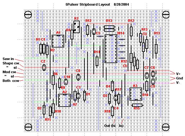
The two figures below give a stripboard layout that works well. The color coding for the first figure is as follows: The light red, green and violet lines are merely visual guides showing the main power supply routing. In black are shown the topside components and jumper wires. The light blue features are on the bottom (land) side of the board. The x's denote breaks in the traces and the lines indicated soldered bus wires that ground the unused traces. The second figure is a (reversed) view of the bottom of the board. Note that the circuit fits comfortably on a 47 x 39 grid.
Version 2
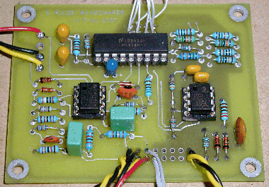
Version 2 uses different input circuitry, to convert the +/- 5 V input to 0 to 1 V. The modified circuit, a photo of a PC board that has been designed for it and more sound clip are given below.
Sound clip 1
Sound clip 2
Sound clip 3
Back Home


