Double-Pulse Waveform Generator (I)
Here is a waveshaper circuit that produces unique timbres not available with conventional (sawtooth, triangle, pulse) synthesizer waveshapers. The standard sawtooth and pulse waveforms have strong overtone series including both even and odd harmonics. On the other hand, the standard triangle and square waveforms have just odd harmonics, but at only moderate strength. Waveforms with strong, odd-only harmonics are not available with traditional waveshapers. These "missing" waveforms combine the "buzzyness" of pulse waveforms with the "hollowness" of triangle and square waveforms.
Odd-only harmonics may be obtained by combining symmetrically placed positive and negative pulses. With such "antisymmetric" waveforms, the even harmonics from the two pulses cancel, leaving only odd harmonics. The strength of the upper harmonics increases as the pulse width decreases, just as for an ordinary (single) pulse waveform.
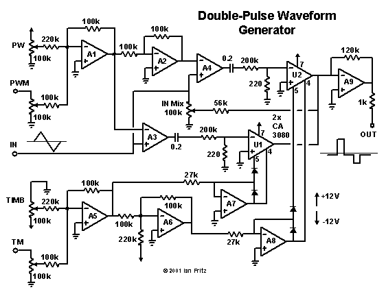
The circuit below produces a variety of useful non-traditional waveforms, including antisymmetric double pulses. It has been part of my modular system since 1977. An experimental version of the core circuitry was presented in Electronotes #72.
To explain the circuit's operation, I will assume it is driven by a triangle wave, as indicated. The input signal drives the non-inverting inputs of the two comparitors A3 and A4. A threshold voltage and its inverse are produced by the pulse-width (PW) control and the inverting amplifiers A1 and A2. These are fed to the inverting inputs of the comparitors. The output of A4 is a positive-going pulse generated while the input voltage is above the threshold voltage. Similarly, A3's output is a negative-going pulse generated while the input is less than the negative of the threshold.
These two pulses are dynamically mixed by the complementary voltage-controlled gain blocks consisting of A5, A7, U1 and A6, A8, U2. Here I have used the method developed by W. Jung of driving the CA3080 transconductance amplifier through its negative supply pin. The unconventional pin usage is indicated in the figure. The timbre control (TIMB) allows the output waveform to be continuously varied between a single pulse and an antisymmetric double pulse. The pulse width and asymmetry can both be modulated by appropriate control voltages via the PWM and TM inputs.
To further increase the range of timbres available, the control labeled "IN Mix" has been included in the circuit. This control allows some of the input signal to be subtracted from the output, reducing the strength of the lower harmonics compared to the higher ones. This produces an effect somewhat similar to high-pass filtering.
Many variations on the basic ideas presented above are possible, including variable pulse spacing, unequal pulse widths, the use of more than two pulses, voltage control of the IN Mix parameter, etc. However, the circuit as shown covers a lot of interesting timbres and is a good starting place for exploring sounds not available using traditional waveshapers.
Back Home

