The "SNICster" Waveform Generator
Sawtooth and triangle wave shapes are commonly available in most analog synthesizers. A capability to continuously deform one into the other is often desired, but is not easy to implement. On this page, I present a novel method of producing such a variable waveform. The method uses a "saturating negative impedance converter", or SNIC. Negative impedance converters are widely used for design of high-performance filters, but they can also be used for a variety of waveshaping applications and have been an important component for constructing electronic nonlinearities for chaos generators.
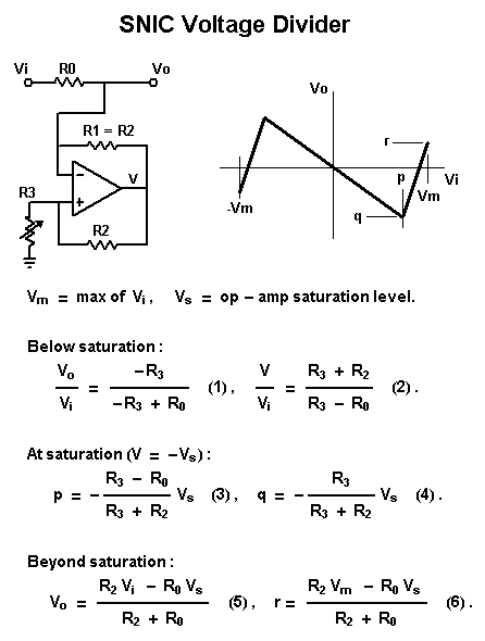
The present waveshaper uses a voltage-controlled SNIC as the lower leg of a voltage divider. The basic behavior of such a circuit is illustrated in the first figure. In this circuit the resistor R0 is the upper leg of the divider and the rest of the circuit, a textbook negative resistor, is the lower leg. A negative resistor can only operate over a restricted range of voltages, in the present case limited by saturation of the op amp. At large voltages it must present a positive differential resistance. Therefore, the transfer function of the voltage divider will have the general appearance illustrated to the right of the schematic.
Analysis of the circuit is straightforward. It is necessary to perform separate analyses for the unsaturated and saturated regimes. Below saturation the circuit is easily analyzed using the usual "golden rules" for op amp circuitry. The results are given in Eqns. (1) and (2). Note that the lower leg of the divider has an effective resistance of -R3. At the saturation point, the input and output voltages are given by the quantities p and q expressed by Eqns. (3) and (4). It may be pointed out here that the saturation point can be determined by the op amp characteristics or, aternately, by external clamping circuitry, as will be used further below. Beyond saturation, the op amp output voltage is fixed, and the transfer function is determined by passive voltage division, resulting in Eqns. (5) and (6). Here we note that the output voltage produced by the maximum input voltage is denoted as r. This quantity will be zero for the sawtooth to triangle wave bender under discussion here, but may be non-zero in other wave shaper applications, such as wave folders.
The figure below indicates how the general results presented above are specialized to the SNICster waveshaper. We use a +/- 5 V driving signal, a clamping voltage of 9.3 V to set the saturation point and feedback resistors of 100 k. The condition r=0 for endpoint continuity then determines the value of R0. The values of R3 required to produce either sawtooth or triangle waveforms and the resulting peak output voltages are then easily calculated from the equations above. Note that the output amplitude changes by a factor of two across the sweep range. The final circuit compensates for this variation with a voltage-controlled amplifier (VCA).
To make a practical waveshaper module, we need to incorporate a voltage-controlled resistor for the variable resistor in the above panels and to add circuitry to level the final amplitude. In addition, a much richer variety of waveforms can be made available by simply adding (or subtracting) the initial and final waveforms. The final module includes a polarity-reversing switch and another VCA for this admixture. This part of the module may be omitted if the sawtooth-triangle bender is all that is needed.
The circuitry for the audio path is shown in the figure below. The upper leg of the SNIC divider is R2, which is trimmed for proper continuity at the ends of the waveform (r=0). Input and output buffering of the SNIC circuitry is provided by A1a and A1b. The NIC is built around A2, with U1 and associated components being the variable resistor. External clamping of A2's output is provided, so that the module can be powered by various supply levels. Leveling of the output amplitude is accomplished with the VCA built around U2a and A3a. R16 is trimmed to produce a +/- 5 V output in the sawtooth-waveform limit of the shaper.
The remainder of the audio circuitry is optional and provides for mixing a variable amount of the input with the main signal. The function of A3b and associated components is to provide polarity switching into the final mixer, A3c. U2b and A4d are used to make a VCA to vary the admixture of the input signal. Depending on the driving waveform and the position of the polarity switch, the mixed output may exceed the nominal 5 V level of the module. The clamp attached to the mixer limits the output in this situation.
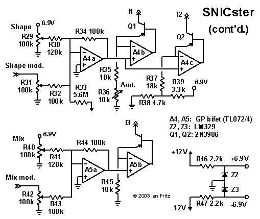
The figure below presents the control circuitry for the three OTAs. A4a sums the control voltages that set the SNIC divider's wave shape and amplitude. The current source built around A4b and Q1 provides the correct range of current to vary the current-controlled resistor (U1, etc.) between 54 k and 21 k, as required to vary the output waveform from sawtooth to triangle. At the same time, the current source built around A4c and Q2 varies the control current I2 over a range of about 2:1 to provide amplitude leveling via the U2a/A3a VCA. As shown, only a single trimming adjustment, R36 is provided for the I1/ I2 current sources. In practice, this trimmer is set to level the output amplitude vs. control voltage. With the components shown, this results in a waveshape that can be tuned to somewhat beyond the triangle limit. The final circuit block is built around A5a and A5b and produces the the control current for the U2b / A4d VCA, i.e., for the mixing of the original signal with the main shaper output.
One of the interesting features of the SNIC shaper is that, in the sawtooth limit, the output is in quadrature with the input sawtooth. This means that the input and output may be combined to produce either a frequency-doubled sawtooth or a square wave. The final figure shows the limiting waveforms that can be produced by the SNICster. To read these graphs, just examine the central portion of each waveform (in blue) to see the response to an input sawtooth wave and the entire waveform to see the response to triangle-wave drive.
Demo:
This clip demonstrates the range of timbres available from the SNICster. For this demo two random sets of stepped control voltages were sent to the two control inputs. There are four sections demonstrating the combinations of tri/saw driving input and the two summing polarities.
Back Home