Hybrid Synth System Details

The block diagram below shows the layout of the audio section of my hybrid (digitally controlled analog) synthesizer. The audio section is "normalized" in the sense that there are no patch-cord points for interconnecting the modules. However, the three voltage controlled mixers (MXR1,2,3) provide a reasonably flexible interconnection scheme. For example, note that the filters can be connected in series. More usually, though, the filters are used in parallel paths, one of which defines the sustained part of the sound while the other defines the transient part, as illustrated in the "Up Close" section.

There are two kinds of control inputs to the various modules. First, there are parameters derived from the wind-controller interface, i.e., under the player's control. An example would be a filter cutoff frequency that increases with breath force. Second, there are parameters that are set and held by the computer. These determine the playing characteristics of the patch. An example of this would be the same filter's initial frequency. The solid circles and the x's indicate these two types of control inputs. The letter "M" in the diagram indicates computer control of the mode of a module, for example the type of filter response (PB, LP, or HP).

Audio path

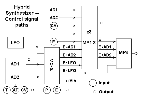
The second figure is a block diagram of the synthesizer's control-signal section. The signal inputs to this part of the system come from a circuit that interfaces with the wind controller and which generates the control signals CV, E, T, AT and P (all discussed in the "Up Close" section). The diagram indicates how a further extended set of control signals is generated. First, there is circuitry for the two envelope generators AD1 and AD2 and for the LFO. The block marked CVP (control voltage processor) includes dedicated multipliers for generating the envelope- and pressure-modulated signals (E x AD1, etc.). The signal marked "Vib" is a mixture of LFO and P X LFO. Finally, four voltage controlled mixers serve as "modulation processors" MP1-4. These mix various combinations of control signals which may be connected to the different modules in the audio signal path. Although not explicitly indicated, the parameter setting for the individual blocks in this diagram are all under computer control. The control-signal section has eight outputs, indicated by the small open circles.

Control path

The connections between the control section and the audio section are made via a matrix arrangement, using computer-controlled switches. This matrix connects the closed (input) circles of the first figure to the open (output) circles of the second figure, according to the scheme in the figure below.

Modulation matrix

The connections indicated by X's are switched under computer control and those indicated by squares are permanent. For example, MP4 is always connected to VCA1, and may be additionally connected to VCF1. Note that only certain connections are possible, i.e., it is not possible to connect each control signal to every audio module. However, most modules can be connected to several control lines, and since the modulation processors MP1-4 are mixes of control signals, the system's control signal routing is quite flexible.

Switched Mode Settings
Module Data 0 Data 1
AD1,2 AT T
MP1-3 E x AD1 AD1
MP1-3 E x AD2 AD2
DPWG + / - + / +
VCO2 --- Sync
VCF1 --- LP
VCF1 --- HP
VCF1 --- BP
VCA1 Lin Exp
The system's computer-controlled switching array defines the control signal routing as just discussed, and in addition it sets the mode of operation of several of the analog and control modules. These "switched mode setting" are listed in the first of the tables here. Two of the switches set whether the AD generators are driven by T or AT. Six select between AD and E x AD at the modulation-processor inputs. One determines whether the DPWG output pulses are of the same or opposite polarity. Another allows VCO2 to be synched to VCO1. Three more select the mode of the state variable VCF, and finally one selects between linear and exponential VCA1 response.

Analog Parameter Settings
Module Parameters
AD1,2 Att. t, Dec. t, Delay t, CV scaling
LFO Freq.
CVP Vib. amount
MP1-3 (E x)AD1, (E x)AD2, LFO, P x LFO, E, CV (mix)
MP4 E x AD1, E x AD2, E x LFO, E (mix)
VCO1 Init. F, FM depth
DPWG PW, PWM depth, PP, PPM depth
VCO2 Init. F, FM depth, PW
AMX1 Saw1, Tri1, DP, Saw2, Tri2, VCF2 (mix)
AMX2 Saw1, Tri1, DP, Saw2, Tri2, Pul2 (mix)
VCF1,2 Init. F, Q, FM depth
VCA2 Init. A, AM depth
The system's computer interface sets and holds 63 analog voltages which establish various voltage-controlled parameters in both the audio and control sections, as discussed above. A complete listing of these is given in the second table. There are just a couple of points to be specially noted in this table. First, the AD generators have voltage controlled delay times and their rates can be scaled to the main control voltage CV. Second, the width and relative position of the DPWG pulses are under voltage control. Thus pulse position modulation is available in addition to the more familiar pulse width modulation. The remaining functions should be self-explanatory to those familiar with standard synthesis techniques.


Back   Home