The Stealth Mouthpiece Circuit
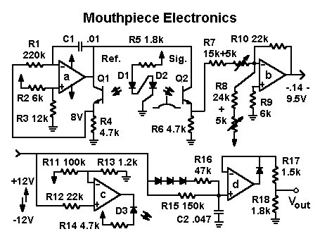
The basic principles of the mouthpiece circuitry are described on the "EZ Mouthpiece Electronics" page. The full circuit shown below adds 1) a servo-controlled current source to stabilize the photodetector against temperature variations, 2) a threshold indicator for setting the output offset and 3) an asymmetric lag circuit to prevent the output from changing too rapidly.
 The optoelectronic circuitry consists of two LED-phototransistor pairs, D1-Q1 (reference) and D2-Q2 (signal). Consider first the quiescent state, with no blowing pressure and equal light intensities in the signal and reference paths. The LED's are connected in series, so they have the same current and, if properly matched, the same light output. On the "reference" side of the circuit, Q1 is in the feedback loop of the "a" op amp, whose output goes to whatever voltage is necessary to hold Q1's emitter at 8 V (as set by the R2-R3 voltage divider). This same voltage supplies the collector voltage of Q2, on the "signal" side. If Q2 is matched to Q1 and they each receive the same illumination from their respective LED's, then the emitter of Q2 will also be at 8 V. As temperature varies, the op-amp output varies, but the emitter of Q2 stays very close to 8 V.
As in the "EZ" circuit, an increasing blowing force causes the D2-Q2 light path to be progressively blocked, causing the voltage across R6 to decrease to near 0 V. Op amp "b" inverts, scales and offsets this voltage to a range of -0.14 V to +9.5 V. The gain is set by R7 and the offset by R8. The circuit around op amp "c" turns on LED D3 when the -0.14 V threshold is crossed. The purpose of this circuit is simply to allow visual checking of the offset without hooking up a meter.
The output circuit (op amp "d") rectifies and limits the signal so that it has a fixed total excursion. When "d" saturates, the top of R17 is at 9.5 V, so the cutoff of Q2 and the saturation of op amp "d" occur at the same point. This point should also correspond to the maximum desired blowing force and breath flow rate, as well as to the maximum diaphragm displacement. That way, all the parts of the system work together consistently.
Capacitor C2 slew limits the output to prevent popping in the synthesizer circuits. The slew rate is set by R15 for slow signal changes and by R16 when the signal increases rapidly, turning on the three series diodes.
Back Home
 The optoelectronic circuitry consists of two LED-phototransistor pairs, D1-Q1 (reference) and D2-Q2 (signal). Consider first the quiescent state, with no blowing pressure and equal light intensities in the signal and reference paths. The LED's are connected in series, so they have the same current and, if properly matched, the same light output. On the "reference" side of the circuit, Q1 is in the feedback loop of the "a" op amp, whose output goes to whatever voltage is necessary to hold Q1's emitter at 8 V (as set by the R2-R3 voltage divider). This same voltage supplies the collector voltage of Q2, on the "signal" side. If Q2 is matched to Q1 and they each receive the same illumination from their respective LED's, then the emitter of Q2 will also be at 8 V. As temperature varies, the op-amp output varies, but the emitter of Q2 stays very close to 8 V.