The Stealth Octave Key Circuit
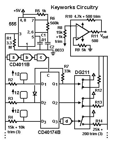
The touch-key circuitry is shown in the figure below. When a key is touched, the player's body capacitance is added to the capacitance of the key. This change in capacitance changes the relative timing of electrical pulses being sent to a latch circuit, thereby switching the output state of the latch. The latches activate CMOS analog switches, which drive current into the output op-amp circuit, as described in the "Keyworks Circuit Principles" page.
 The timing pulses are sent by a 400 Hz oscillator built around the 555 timer seen in the diagram. The 555 provides a stiff output signal that can drive many keys in parallel. The pulses are delayed by the internal propagation delays of stages a, b and c of the CD4011B (other inverter chips could be used, of course) and then applied to the clock (C) inputs of the CD40174B's latches. The data (D) input of the latches are also taken from the oscillator, except now through the RC lag networks formed by the resistors R2, R3, R4 etc., and the keypad capacitances. Fingering a key produces a delay that is longer than the delay of the inverter chain, thereby switching the latch output.
The values of the lag resistors depend on the size of the keypads and on the circuit layout. There is also a little bit of interaction among the circuits, so the lag resistors need a fair range of adjustability, and they have to be carefully trimmed to get a uniform (leveled) response across all the keys. It is also important to keep the leads from the pads to the circuitry separated from each other to avoid crosstalk.
The operation of the touch-sensitive circuitry depends on the specific type (family) of logic circuit used. I found that B-series CMOS seemed to work best. Other families tended to exhibit a very slight sensitivity to ac (line frequency) pickup right at the switching point. I don't think this would be a practical problem, but the effect was not seen at all with the B-series. For the latches, either the hex 40174 or the quad 40175 IC's can be used. The 40175's have both inverted and non-inverted outputs available, allowing the inverter shown at the Q3 output to be eliminated.
The diagram only shows the circuitry for the thumb keys, as these illustrate all the important principles needed for the entire circuit. The top key -- connected to the D1 input of the latch -- is one of the compound-action keys described on the "Fingering System" page. Actuating this key opens the topmost analog switch, which shifts the pitch up an octave. At the same time, the resistor-diode combination connecting Q1 to D2 actuates the second latch, moving the pitch up another octave. If the second key is already being pressed, then this feedback simply has no effect. Pressing the second key alone moves the pitch up an octave, and pressing the third key moves the pitch down an octave, as the inverter (d) normally keeps the associated switch open.
The extension of the circuit to include the other keys can be done in a straightforward manner, once the above principles are understood. The trimmers shown with the resistors R12-R14 are used only with the octave keys. Using matched resistors of the proper values for the rest of the keys provides tuning that is accurate enough.
Back Home
 The timing pulses are sent by a 400 Hz oscillator built around the 555 timer seen in the diagram. The 555 provides a stiff output signal that can drive many keys in parallel. The pulses are delayed by the internal propagation delays of stages a, b and c of the CD4011B (other inverter chips could be used, of course) and then applied to the clock (C) inputs of the CD40174B's latches. The data (D) input of the latches are also taken from the oscillator, except now through the RC lag networks formed by the resistors R2, R3, R4 etc., and the keypad capacitances. Fingering a key produces a delay that is longer than the delay of the inverter chain, thereby switching the latch output.