Keyworks Circuit Principles
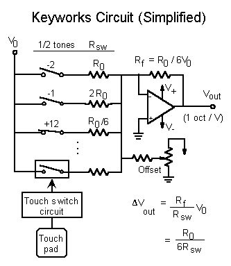
 This diagram is a generic rendering of a single op-amp circuit for producing a standard 1 octave / volt control signal from an arbitrary collection of keys. The keys operate switches -- indicated along the left side of the diagram -- that may either be mechanical (upper three) or electronic (bottom).
Each switch connects the reference voltage V0 through a resistor Rsw to the op amp summing node. Suppose a switch that is normally open gets closed. Since the summing node is a virtual ground, the current flowing into the summing node is increased by an amount V0 / Rsw. Since no current can flow into the op amp input, this extra current must flow out of the summing node, through the feedback resistor Rf to the op amp output. The output must go to a lower voltage to draw the extra current. The equation in the drawing gives this voltage decrease.
Note: The change in output voltage does not depend on what it already is. In other words, a given key closure always changes Vout by the same amount, independent of which other keys are closed. Thus each key represents a certain musical interval, and the effect of pressing multiple keys is to add all the corresponding intervals together.
To design an actual circuit proceed as follows: First decide on a key layout and on what interval each key is to represent. Next pick values for the reference voltage V0 and for the resistor R0 (which represents an interval of a whole tone). Five volts and 150 kohm work well. Keys representing a semitone require a resistance of 2R0 (300 k), octave keys require R0/6 (25 k) and so on. Finally calculate the feedback resistor from Rf = R0 / 6 V0. (With the already suggested values, this is 5 k.) Rf needs to be slightly adjustable to trim the response to exactly 1 oct / V.
The resistors of the offset network set the output range of the circuit. Typically, the lowest note on the controller would be set near zero volts. First figure out the equivalent parallel resistance of all the switched resistors. The resistor from the summing node to the trimmer's wiper should be about twice this value (assuming the supply voltage is 2-3 times V0).
Back Home
 This diagram is a generic rendering of a single op-amp circuit for producing a standard 1 octave / volt control signal from an arbitrary collection of keys. The keys operate switches -- indicated along the left side of the diagram -- that may either be mechanical (upper three) or electronic (bottom).