PIC Microcontroller Circuit
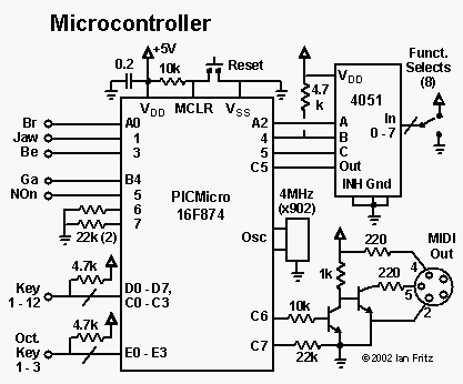
 The connection of all the sensors, keys and configuration switches to the PIC microcontroller is illustrated in this diagram. Port A is configured with lines A0, A1 and A3 as analog inputs that measure the breath, jaw and bender signals, respectively. Lines A2, A4 and A5 are digital output lines that address the CD4051 multiplexer connected to the eight "function select" or instrument-configuration switches.
Port B is configured to generate "interrupt on change" on lines B4-B7, and the gate and note-on signals are connected to the first two of these. When used, the note-off trigger is connected to B6. Port C is used for three separate functions. The first four lines are connected to the keyworks, along with the eight lines from Port D and the three from Port E. C5 reads the setting of the configuration switches, and C6 and C7 are configured for USART operation.
Also shown on the diagram are a reset switch, a ceramic resonator for 4 MHz clock operation and a two-transistor MIDI output circuit.
Back Home
 The connection of all the sensors, keys and configuration switches to the PIC microcontroller is illustrated in this diagram. Port A is configured with lines A0, A1 and A3 as analog inputs that measure the breath, jaw and bender signals, respectively. Lines A2, A4 and A5 are digital output lines that address the CD4051 multiplexer connected to the eight "function select" or instrument-configuration switches.