Bender Circuit
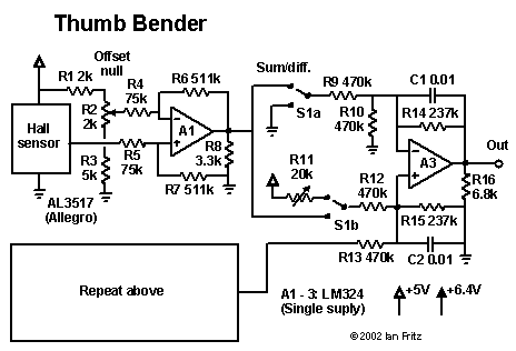
 This diagram shows the thumb bender circuit. The thumb bender consists of two spring strips whose positions are monitored by linear Hall sensors. Two identical circuits amplify the sensor signals, as shown in the left-hand part of the diagram. The two signals are combined by the generalized summer constructed around A3. This summer can be switched to either measure the difference between the signals (upper switch position) or the sum of the signals (lower position). For the differential case, the quiescent output is set at 2.5 V as is appropriate for bipolar MIDI commands such as MIDI pitch bend. In contrast to the jaw circuitry, there is no dead zone used for the bipolar case, as no force is required for centering the signal. The trimmer R11 is used to set the center point precisely.
With the switch in the lower position, the circuit output is the average of the output of the two sensors. Maximum range is obtained by pressing both strips, whereas a finer control can be obtained by using just one of them.
Back Home
 This diagram shows the thumb bender circuit. The thumb bender consists of two spring strips whose positions are monitored by linear Hall sensors. Two identical circuits amplify the sensor signals, as shown in the left-hand part of the diagram. The two signals are combined by the generalized summer constructed around A3. This summer can be switched to either measure the difference between the signals (upper switch position) or the sum of the signals (lower position). For the differential case, the quiescent output is set at 2.5 V as is appropriate for bipolar MIDI commands such as MIDI pitch bend. In contrast to the jaw circuitry, there is no dead zone used for the bipolar case, as no force is required for centering the signal. The trimmer R11 is used to set the center point precisely.