The Son of Stealth Up Close
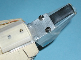
The photo on the left shows a side view of the controller. At the top is the mouthpiece, fashioned from a single piece of plexiglass. Below the mouthpiece are two circuit boards carrying the mouthpiece electronics, followed by the left-hand keyworks. The left-hand support is seen on the right side of the photo.

|

|
The upper circuit board amplifies the transducer signal and derives the envelope gate, and the lower board provides the slope detection and emphasis functions.
 To the left is seen a closeup of the jaw sensor. The sensor is built on a thin plastic platform that is wrapped with rubberized black fabric and glued into a slot in the bottom of the mouthpiece. This packaging keeps the Hall sensor and its attached electrical leads dry.
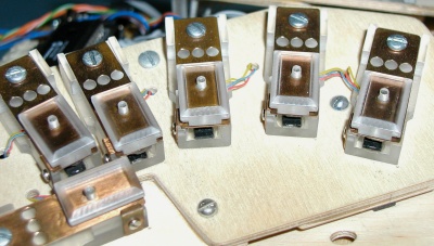 Here's a closer view of the left-hand keyworks. The body of each key is a machined block of plexiglass. A strip of spring-brass with a plastic top cap at the finger end is attached near the back of the body. The three holes in the metal strip define the bending point and the spring force of the key. The downward travel of the key is limited by the block, and the upper travel is limited by a brass finger attached to the side of the block. Also mounted to the block is a Hall-effect switch, seen near the front. Above the sensor and glued to the spring strip is a rubber magnet that is shaped to provide switching near the middle of the key travel.
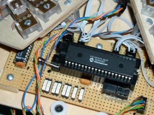 Below and under the keywork assemblies is a circuit board with the instrument's brain. This consists of a PIC microcontroller (the large chip), a set of slide switches for setting the instrument configuration (eight white rectangles) and a chip for interfacing the switches. The output of this circuit is attached to a standard MIDI DIN connector (not shown).
 This photo shows the back of the instrument. On the upper left are the three octave keys, operated by the left thumb. These operate by the same rocking and rolling motion as used in the Stealth. Towards the upper right is the bender unit, which consists of two spring-actuated force sensors operated by the right thumb. Below these in the photo are two circuit boards, the one on the left for the jaw transducer and the other for the bender unit. Notice that each has a switch to select bipolar or unipolar operation.
Back Home