Chaos: General Remarks and Implementation
BackgroundWhat exactly is chaos, anyway? As with many terms, its technical meaning is different from that in everyday usage. Broadly speaking, a chaotic system is one where the system's variable quantities satisfy deterministic mathematical equations (i. e., present values may be calculated from past ones), while at the same time being highly irregular, but still contained within a finite region (the "strange attractor").
In an electronic circuit, the variables are time-varying voltages at different circuit nodes. Generally, these are plotted parametrically (i.e., voltage 1 vs. voltage 2 as time is varied.) In a deterministic system, the path followed by the variables cannot cross itself, therefore a chaotic system must be at least three dimensional (third order or higher). As a special case, one of the variables may be a time-dependent driving force or signal. Thus, where the traces seem to meet and cross in the parametric plots, they are actually crossing one above the other, utilizing a third dimension (voltage 3).
Electronic Implementation
In making an electronic circuit exhibiting chaos, one is essentially making an analog computer for the differential equations describing the system. This means that circuits that can differentiate a voltage are needed. In practice, it is convenient to actually do this with electronic integrators, the idea being that the input of an integrator is the derivative of its output. In addition, a nonlinear circuit element must be incorporated, as linear systems cannot be chaotic.
Many chaotic electronic circuits have been developed, and chaos was even observed in some the earliest work on vacuum-tube electronics. Most studies on chaotic circuits have been aimed at developing simple circuitry. In the present work we emphasize more complicated chaotic systems with variable patterns and evolution rates, which allow a wide variety of resources for potential musical applications.
General Implementation Techniques
Variable-rate integrators can be built using operational transconductance amplifiers (OTAs), in the same way that OTAs are used in variable-frequency filters for electronic-music applications. Simple nonlinearities using the response of inexpensive components such as diodes, zener diodes and opamp comparitors can produce useful results, avoiding the necessity of complicated break-point or electronic multiplier circuits.
A high-performance variable-rate integrator can be built using an operational transconductance amplifier (OTA) followed by an opamp integrator. What remains to be explained is how to relate this response to the mathematical differential equations and the requisite nonlinear circuit element. The following figures illustrates a typical example of how this may be done.
The first figure illustrates a voltage-controlled damped integrator, which may be used to implement one of the coupled first-order differential equations of a chaotic system. The OTA multiplies its differential input voltage by a factor proportional to its control current to produce an output current Io. Characterizing the OTA as an effective resistance ROTA yields Eqn. 1. Equation 2 describes the response of the opamp integrator, whose output is a voltage ramp with rate proportional to Io and thus to the control current Ic. Combining the first two equations results in Eqn. 3.

In Eqn. 3, note that time occurs as a single factor on the left side. Thus by rescaling the time variable, we may cancel the two prefactors on the right side. The form of the scaled equation is then independent of the OTA control current. This means that the shape of the attractor is independent of the rate (or "frequency") of the system. Rewriting the result in a more mathematical-looking manner results in the boxed equation. Here, the time derivative of x is equal to a damping (negative feedback) term plus a term coupling x to a second variable y. Coupling to other variable can be done by providing additional input resistors connected to the (+) and (-) OTA inputs.
The boxed equation may be represented by the highly schematic drawing in the lower box, from which the correspondence to an actual circuit is clear.
 For a representative nonlinear circuit element, we will use the circuit in the adjacent figure. The transfer function of this circuit (after appropriate scaling of the voltage variable) is similar in shape to the function x(1 - x2). This function is of interest because of its occurrence in many physical systems, e. g., those with double well potentials. The response curve of this circuit is smooth and rounded because of the soft knee of the zener-diode response.
An Example System
An example of the above methods is shown in the next figure. The block diagram follows immediately from the system of equations. From the diagram we see that the circuitry needed consists of three integrators with identical damping, connected in a loop with a nonlinear element of the kind described above plus an additional cross-connection represented by the 1/a signal path.

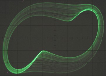
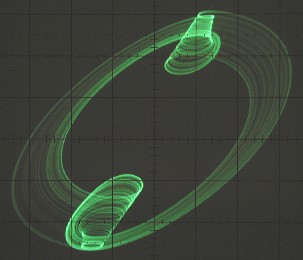
This system has been patched up using the circuitry described in the "Schematics" section. The scope shots below show the x-z and y-z projections of the chaotic attractor for a particular combination of damping and coupling parameters. Below the photos are the results of a simulation carried out by solving the system differential equations using the Mathematica programming language. Parameter values are a = 0.4, b = 0.4956 and c = 1.1. The agreement with the observed attractor is remarkably good, given that circuit nonidealities can significantly modify the system behavior and that the analytic nonlinear response is approximate.
 |
 |
 |
 |
Here is a brief demo sound clip of this attractor controling a synthesizer patch.
Back Home