Traveling-Wave Chaos
Usually you read about chaotic circuits that are either self-oscillating or are driven by an external Sin(Wt) signal. Here's something in between: a second-order system driven by a traveling-wave signal given by Sin(kx - Wt).
To implement this we start with a system having two cross-coupled integrators. One of the circuit nodes has a voltage we call x(t) and another has a voltage proportional to the time derivative of x, which we will call x'(t). From the x' signal we derive a signal kx' - W (by multiplication and subtraction). This signal is the time derivative of the driving signal's phase, kx-Wt, or equivalently, its instantaneous frequency.
To obtain the driving signal itself we run the instantaneous frequency signal into the linear FM input of a thru-zero FM VCO. This works because the VCO core is based on an integrator. It integrates the input instantaneous frequency signal, giving a ramp signal with slope proportional to the signal's phase. The ramp reverses direction whenever the signal reaches its voltage limits (ie, +/- 5V). This triangle-wave based oscillation may converted to a sinusoidal signal by a standard waveshaper circuit. It turns out that a simple system -- in the present case a damped harmonic oscillator driven by a plane wave -- gives a rich variety of oscillatory and chaotic signals.
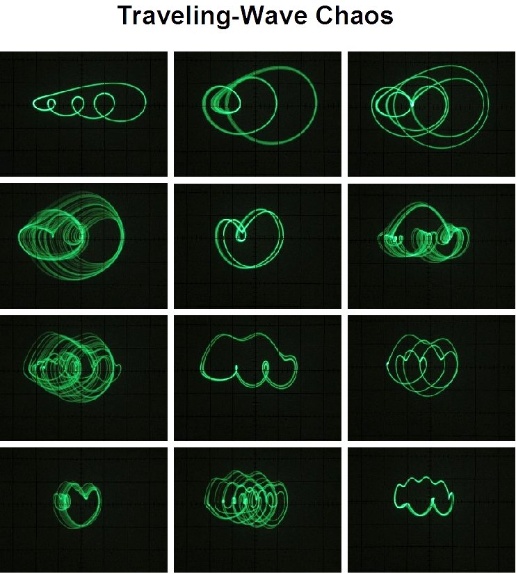
Here are some scope shots taken at different drive frequencies with all other parameters held constant. They represent a small fraction of the interesting patterns that can easily obtained.
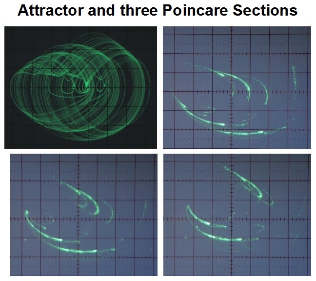
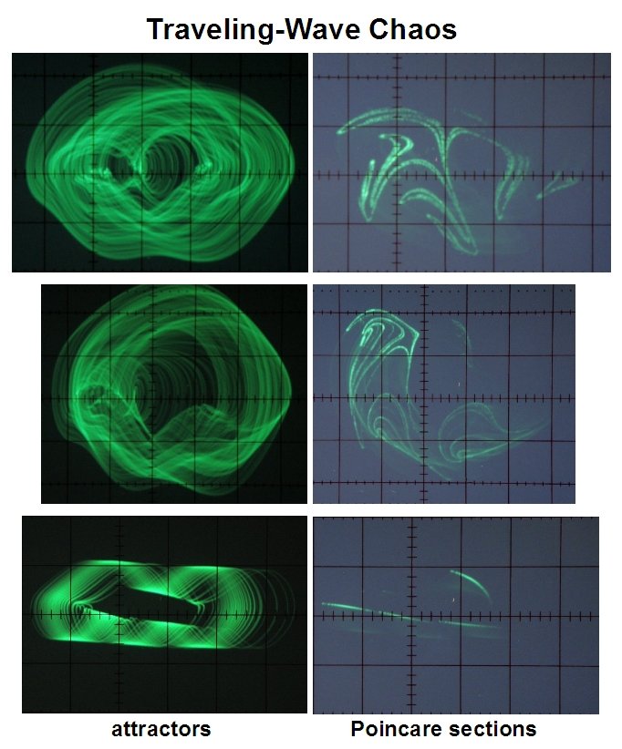
The scope shots below illustrate more results obtained from a traveling-wave chaos circuit. The first figure has a chaotic attractor and three different Poincare sections from near the bottom, middle and top of the attractor. The second figure has three more attractors with their Poincare sections.
The following two figures are schematic diagrams for circuitry to produce traveling-wave chaos. The first figure is the damped harmonic oscillator circuit, and the second is the through-zero FM VCO. This VCO is a new design. It works fine for application in the chaos generator, but has not yet been tested and developed for use as a general VCO module. Note that no Tri-Sin shaper has been included. The Tri drive works very well on its own, although it would make system computer simulations a bit more difficult.
Back Home