Cyclic Chaos System
Chaos can be produced by a number of identical circuits connected in a loop. This is refered to as "cyclic" chaos, since the system equations are identical except for cyclic permutations of the variables. The core circuitry for such a system is shown below. The circuitry around OTA "a" and opamp "a" form a voltage-controlled integrator. Damping of the integrator is provided by feedback through OTA (b), and this damping is also under voltage control. Nonlinearity for the system is provided by the nearly cubic response of the circuitry around opamp "b", as discussed in the "Up Close" section. In the cyclic system, frequency and damping settings are the same for each block. To provide additional patterns, some of the damping loops may be opened up, and some additional cross-couplings of the blocks may be added.
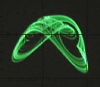
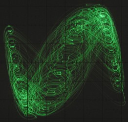
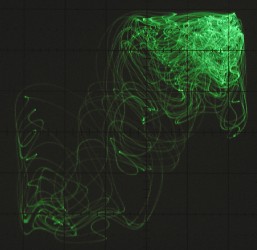
The scope shots below illustrate some of the responses obtained from a fifth-order system at three different damping levels. The patterns are from the first and second stages (first three) and from the first and third stages (second three).
In the remainder of this page, I give some demo sound clips showing some of the system's capabilities.
clip 1:
With the addition of inverters at the five outputs, the system produces signals with ten different phases. For example, when the system makes sinusoidal oscillations, it forms a ten-phase oscillator (decature oscillator?), with the signals separated by 36 degrees in phase. This clip demonstrates the effect of using different phases in a synthesizer patch. The output of section 1 of the generator controls the pitch of a VCO. Two waveforms from the VCO feed two VCAs, whose amplitudes are controlled by the third and fourth sections. The resulting signals are recombined and fed through a VFC, whose frequency is controlled by section 2 in the first part of the clip and by section 5 in the second part. Two distinct sounds are produced, owing to the timing of the filter sweep relative to the VCA sweeps.
clip 2:
An interesting application of the multiple phases of the system is in wave mixing. For this clip, several waveform amplitudes, waveshapes and filter frequencies were varied by five different sections of the generator. The result is constantly varying and slightly irregular sounds.
clip 3:
In this example the chaotic signal is used to trigger different events. The chaotic timing signals are produced by generating trigger pulses whenever a signal crosses a user-defined voltage level. There are several sections in the clip, recorded with different levels of system damping. At the highest damping level, the system is actually periodic rather than chaotic. As the damping is decreased, the system becomes chaotic, then the size of the chaotic attractor increases, bringing in new events and increasing the overall frequency of events. Note that part of the signal gives bursts of events, stemming from the burst-type chaos that occurs in many chaotic systems.
clip 4:
For this example, two sample and hold circuits (refer to the TGTSH page) were incorporated in a patch that includes both chaotic pitch frequencies and chaotic timing events. The first two sections of the clip are identical except for the use of differently phased signals. At first the pitch sequence sounds random, but when the phases are changed the pattern sounds distinctively different. The third section is a variation of the same patch with periodic modulation of the system damping.
clip 5:
This example is similar to the previous one, except that three sample and hold units are used. The two sections of the clip represent two different damping settings
clip 6:
The synthesizer patch used here is the same as in the previous example. A pulsed LFO signal is added to periodically modulate the damping parameter and some cross-coupling between two of the chaos generators stages is incorporated to provide a different attractor.
clip 7:
clip 8:
clip 9:
Three more examples, incorporating four signals from the chaos generator, two sample and hold units along with several synthesizer VCOs, VCFs, VCAs, envelope generators and mixers. The rhythmic component of these examples comes from periodic driving of the sample and hold units.
Back Home